
Introduction:
Hello again, fellow hackers and researchers. Today I’m starting a major series: a deep dive into my reverse engineering journey with the Nokia Beacon 3.1. This router is remarkably hardened, and getting shell access required overcoming significant obstacles. While my research into potential vulnerabilities is ongoing, I’m ready to share the roadmap for accessing root account and exploring the filesystem. If you’re looking to conduct your own security research on this hardware, here is how the journey begins.
Nokia Beacon 3.1 – Key Features:
This device is typically made for easy whole home Wi-Fi extension and is praised for reliable performance and simple app based setup. It’s known by its Mesh Networking, its advanced Wi-Fi features.
The internals are:
1x Gigabit WAN
2x Gigabit LAN.
Dual core 1.6 Ghz CPU
512 Mb DDR.
The problem & mission
At first, I wasn’t very surprised that the UI looked limited and not very user-friendly. I assumed this router was designed for regular users who just want to connect to Wi-Fi and not do much with advanced options. The lack of documentation was also problematic. I found in the user manual that there is a superadmin account, but I didn’t have access to it because each router has its own password, and the same applies to the superadmin account as well.
I called the ISP and asked for the superadmin password. To my surprise, the process was smooth and I obtained it easily. However, the victory was short-lived. once logged in, I found the configuration options were almost identical to the standard user UI. The mission then became clear: I had to find a way to gain true control over the device. It was frustrating to realize that, despite owning the hardware, I was still locked out of my own machine.
Reconnaissance: Mapping the attack surface
A visual inspection reveals this beautiful cup shape:
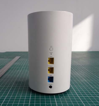
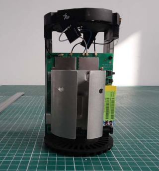
I was impressed by the build quality. The electronics are packed and supported by a heatsink.
It’s clear from the outside that this isn’t a budget router, but does that premium feel extend to the internal software? To truly own this device, I had to find out if the brain was as high performance as the body.
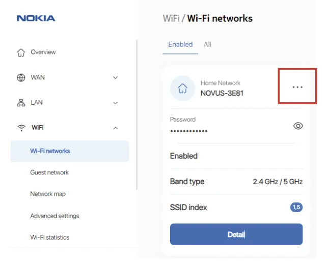
I assume you already know how the UI looks. However, something important I noticed really annoyed me at first: all the payloads in POST methods are encrypted. The frontend is Angular based, and all the traffic between the frontend and the local backend is encrypted. A JavaScript function uses a public key stored in local storage during the browser session to encrypt the data.
I asked myself why they did that, since JavaScript can be modified at runtime using DevTools. What’s the purpose of this?
I came up with two possible answers:
- Ensure the traffic is secure, since almost all routers use HTTP, which makes traffic visible in clear text on the LAN.
- Security through obscurity. I think they also want to make things a little harder for hackers.
In a standard setup, HTTPS handles the transport, but you can still see the JSON in the clear in your Network tab. Here, they’ve added a custom application layer encryption that turns every interaction into an unreadable blob of ciphertext. I have to admit this was the first time I saw the body of POST requests encrypted.
The First Wall : Body Encryption
So the idea is simple, when I’m in front of a router, I try a command injection in ping/traceroute to see if it’s vulnerable. This is a classic approach that every hardware hacker knows. However, to achieve that we have to bypass the first wall which the encryption. The approach is intercept the data before encryption, change it and encrypt it after.
I opened devtool and search for encrypt function in the source code and I found the function responsible to encrypt data. I put a breakpoint in the return instruction and I pressed the “Start test” in the diagnostics page.
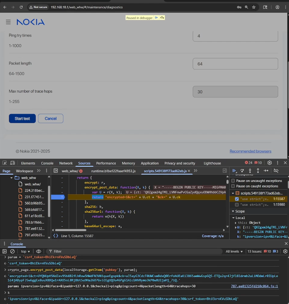
As you can see, now it is possible to see the body in clear text before encryption. The payload was this:
"encrypted=1&ct=1y8fg4CK9-s-ucdzMEVpPof11ocwCWRThTZUIJFMcJcvG5aOBa3HTKfdAfZOU8IYdUwTSFB8KRN2V4oBb80B8VKK4HzUXwWBZalwAuor7ze_wwcgxOLakq9UdpWaSHFTRkyqe9NmlXA44w2ffmAAO7h7X55guHJq-mwvqMKNYP_1hZLuXNoSjqQMgbPkCl-iNXrSjsNhLy5nlynEAsiqbr5pdAKHz3SQg3DTxtZfOkE&ck=RbfmMshNmk2j111DeZVM9IIvpZ2Zo4U03aODWfcr7Gr6jUO8pUodFfmDZMFuoyA33K2T6LDzVsoGWpyXXzIE9Q79wEJ1YCfWRZFCLk668B5Dopti9Ar2IW06yo2-b6n_hExBoJQWqd8CWCeWUNc00D-xuRKLd8evjQ_7jAu7nZI."

// It becomes this:

direction=rx&domain=&ipaddress=&lan_port=LAN1&portstatus=Disconnected&status=enable&wan_port=WAN&wan_conlist=1&waninterfacename=lo|id>/tmp/red1&csrf_token=yyxOKBJGOAUWbvPWWe can patch this by injecting a code that will prompt us the payload modifying it and send it again. I also another method to automate this by using Pupperteer automation API for chromium but you got the idea use your imagination or AI 😉
The Second Wall: UART
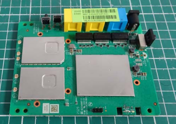
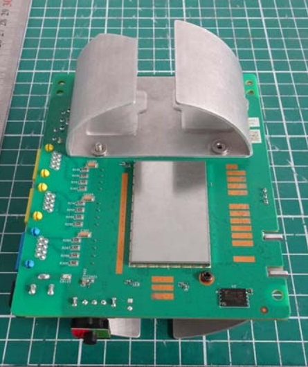
Locating the UART (Universal Asynchronous Receiver-Transmitter) interface is usually straightforward, typically appearing as a row of 3 or 4 unpopulated pins or pads. To map them without a schematic, you just need a multimeter and a bit of patience.
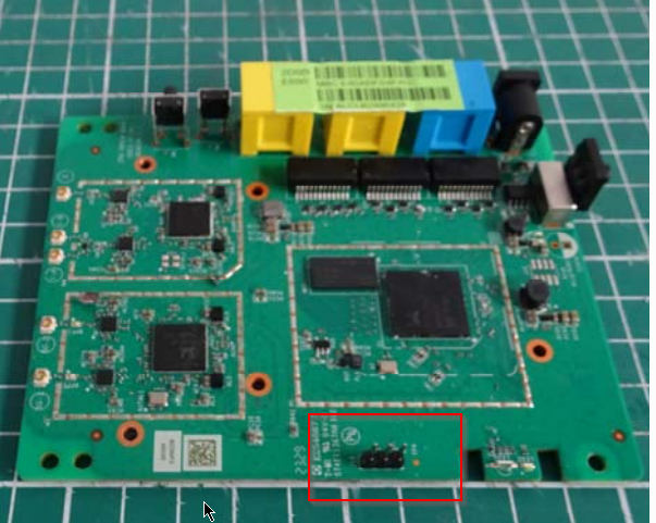
In the image above I found the 3 pads. I connect them using an FTDI. Ensure that you identified the GND first. And for the TX and the RX just try one by one, set the baud rate in your favorite terminal (most of the time is 115200) and voila ✨ 🚀 🤩 ✨
NOTICE: BL31: v1.5(release):gdbd64f1a0-dirty
NOTICE: BL31: Built : 14:42:03, Jul 8 2024
WARNING: Using deprecated integer interrupt arrays in gicv3_driver_data_t
WARNING: Please migrate to using interrupt_prop_t arrays
NOTICE: boot from serial NAND flash
NOTICE: BL31: SPI_NAND: MT29F2G01ABAGDWB/F50L2G41XA/XT26G02ELGIG/WSFVC32GBID 0x2c24
NOTICE: BL31: SPI_NAND: Page 0x800, Block 0x20000, Chip 256MB
NOTICE: BL31: plane_select=0x40, plane_select_bit=0x1000
NOTICE: BL31: SECURE DRAM SIZE is 0x00800000

U-Boot 2020.01 (Jul 24 2025 - 18:35:30 +0800) Taurus-SoC (OPTEE)

CortexA55: 1000 MHz
DDR4-1866: 16-bit mode, 512 MiB

NAND:
  scan_spi_nand_factory_bad_blocks[899]: found list
SPI NAND:
  Model:
  ID: 0x2c24
  Spare: 0x80 (128B)
  Page:  0x800 (2KB)
  Block: 0x20000 (128KB)
  Chip:  0x10000000 (256MB)
  Available: 256MB
  Mode: S/S
  Clock: 100 MHz
  BBL: Bbl0 from flash

Loading Environment from NAND... OK

enter console_disable_check
check_parts[2110]: not change
console_disable_check[48]: SN:
serial_enable = 0
>>>>>>>> Serial console Disabled <<<<<<<<

NOTICE: Booting Trusted Firmware - Realtek Semiconductor Corp.

NOTICE: BL1: v1.5(release): TAURUS_TAPEOUT_2_0
NOTICE: BL1: Built : 17:13:20, Oct 27 2021
NOTICE: BL1: CPU Speed 1000 MHz
NOTICE: GLOBAL_STRAP 0xc0a
NOTICE: boot from serial NAND flash

NOTICE: BL1: Booting BL2
NOTICE: BL2: RTL9607DQ
NOTICE: boot from serial NAND flash

##### DRAM driver version (TAURUS): V0.7.5 #####
INFO: PKG=BGA15
INFO: dram_type = 4
INFO: dram_freq = 933
INFO: dram_dq = 16
INFO: DRAM size = 4Gb
INFO: Done DDR initialization...
INFO: DRAM test PASS
INFO: Address toggle PASS

NOTICE: BL2: v1.5(release): gdbd64f1a0-dirty
NOTICE: BL2: Built : 14:42:03, Jul 8 2024

NOTICE: BL1: Booting BL31
NOTICE: BL31: v1.5(release): gdbd64f1a0-dirty
NOTICE: BL31: Built : 14:42:03, Jul 8 2024
NOTICE: BL31: SECURE DRAM SIZE is 0x00800000

Booting Linux...

[    0.000000] Linux version 5.10.161 (OpenWrt GCC 11.2.0)
[    0.000000] Machine model: Realtek Taurus ENG Board
[    0.000000] earlycon: serial0 at MMIO 0xf43291b0
[    0.000000] Kernel command line:
  earlycon=serial,0xf43291b0
  console=ttyS0,115200
  serial_is_dis=1
  root=/dev/dm-0
  rootfstype=squashfs
  dm-verity enabled

[ 0.000000] serial_is_dis_setup: will disable serialIf you could see closely there is a huge deception in the logs:
>>>>>>>> Serial console Disabled <<<<<<<<Serial communication was working at the beginning, and then it suddenly went silent 😔. Something changed and disabled it without any clear reason. Sure it’s the bootloader. I tried pressing keys, hoping the bootloader would stop and give me a shell, but nothing happened. After the “Serial console Disabled” I had just a quiet screen. The device continue its startup process. Now I have to hunt through hidden settings, flags, and boot stages, trying to find what killed the output and bring it back to life 🔍. Pressing random keys was useless, like the system is refusing to talk 😶
The Point of No Return: Chip Extraction
After checking for JTAG and other interfaces beyond UART, I reached a frustrating point where the only option left was chip extraction. At that moment, it felt like the device was staring back at me, quietly saying “good luck” 😅. This step is always risky, and it requires extreme care to avoid damaging the board or the memory itself. One wrong move and it’s game over 💀. The goal is simple: extract the firmware and analyze it offline. It’s the hard way, but also one of the most effective when everything else is locked down.
At this stage, it became clear that the device is hardened for a reason, and I wanted to understand that reason. The security layers in place are no joke. Every blocked path felt like another challenge. In fact, I’m already impressed, because it feels like the engineers behind this device knew exactly what they were doing and deliberately closed the obvious paths. It stopped being just troubleshooting… and started feeling like a real duel between me and the hardware ⚔️.
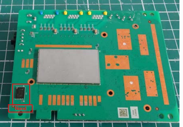
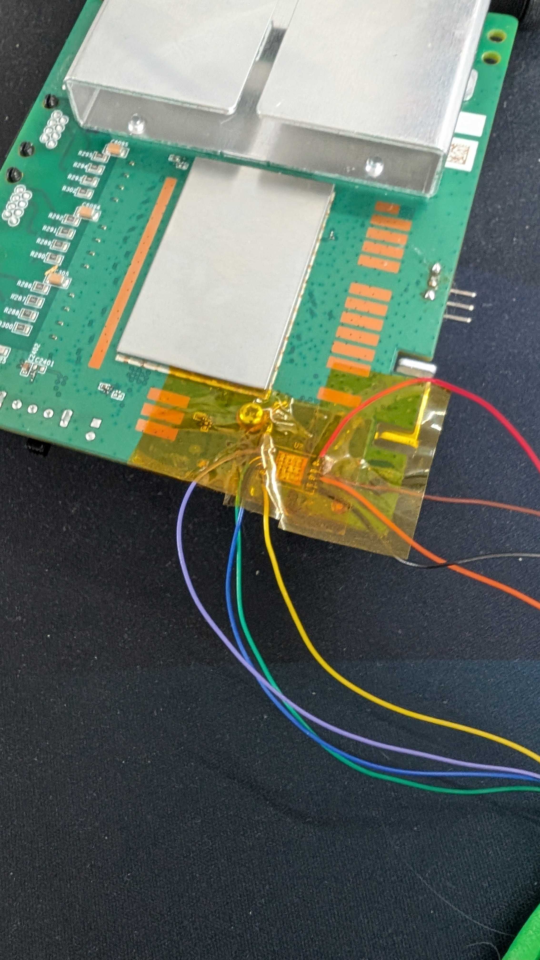
I checked the PCB and googled every chip in the device until I found the one that is a NAND (NW874)
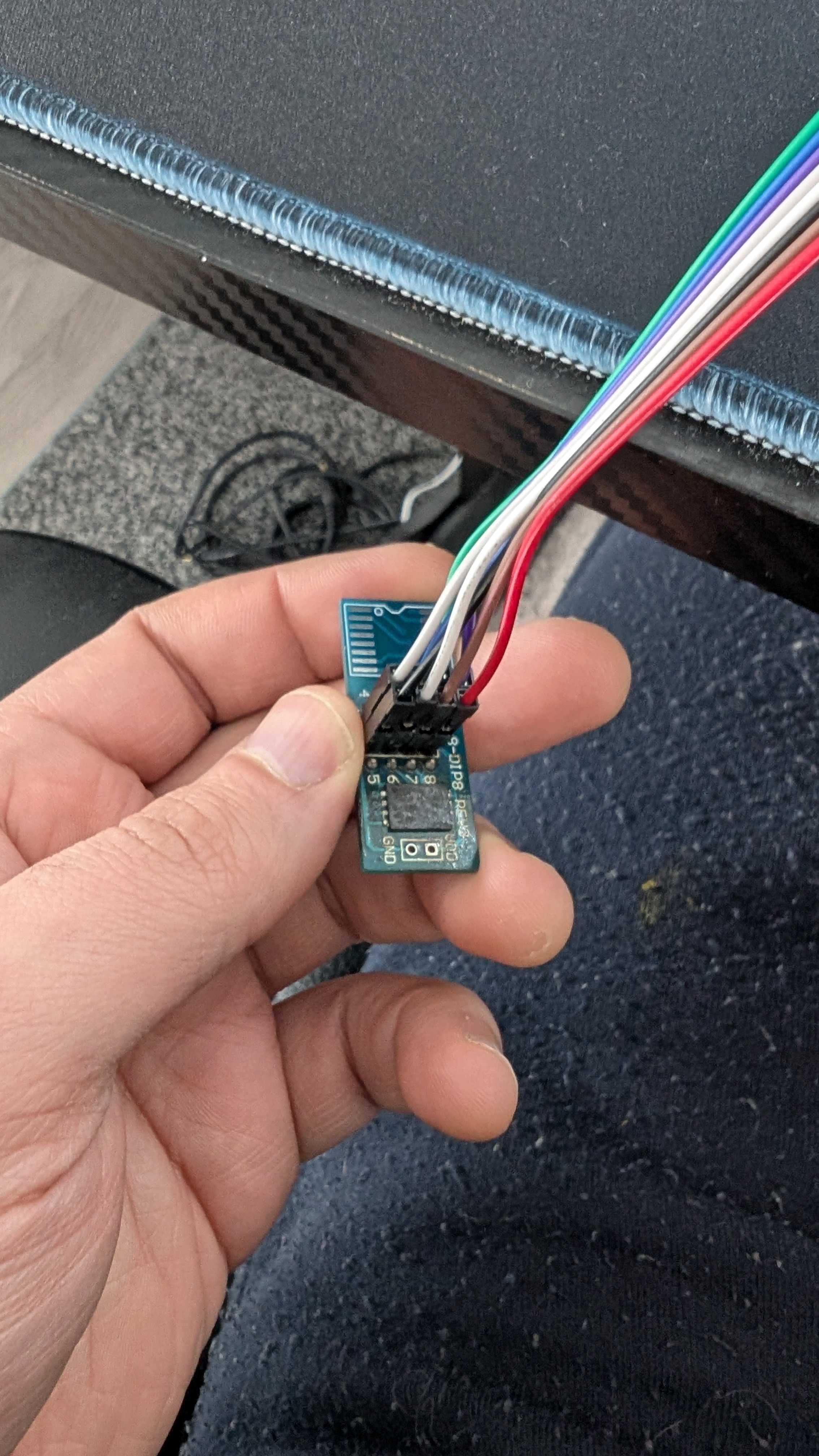
After removing the chip with a heat gun, I didn’t want to take more risks than necessary 😅. My plan was to mount it on an adapter so I could easily reprogram it if something went wrong with the firmware. Once the chip is off, there is no safety net, so having a way back is important. I built a small circuit and carefully soldered wires between the chip pads and the PCB. It was slow and delicate work, and every connection had to be clean. In the end, the setup looked a bit messy, but it gave me control and flexibility in case I needed to recover the firmware later 🔧.
Time to read the chip and see what we will find 😄. This is the part that excites me the most after all the effort. I feel like a child holding a Kinder Surprise, ready to open it and discover what is hidden inside 🍫🎁 The chip is finally about to speak, and I’m watching the process with that mix of curiosity and suspense 🔍⚡.
The firmware landscape:
Going back to the serial output:
NOTICE: Booting Trusted Firmware - Realtek Semiconductor Corp.

NOTICE: BL1: v1.5(release): TAURUS_TAPEOUT_2_0
NOTICE: BL1: Built : 17:13:20, Oct 27 2021
NOTICE: BL1: CPU Speed 1000 MHz
NOTICE: GLOBAL_STRAP 0xc0a
NOTICE: boot from serial NAND flash

NOTICE: BL1: Booting BL2
NOTICE: BL2: RTL9607DQ
NOTICE: boot from serial NAND flash

##### DRAM driver version (TAURUS): V0.7.5 #####
INFO: PKG=BGA15
INFO: dram_type = 4
INFO: dram_freq = 933
INFO: dram_dq = 16
INFO: DRAM size = 4Gb
INFO: Done DDR initialization...
INFO: DRAM test PASS
INFO: Address toggle PASS

NOTICE: BL2: v1.5(release): gdbd64f1a0-dirty
NOTICE: BL2: Built : 14:42:03, Jul 8 2024

NOTICE: BL1: Booting BL31
NOTICE: BL31: v1.5(release): gdbd64f1a0-dirty
NOTICE: BL31: Built : 14:42:03, Jul 8 2024
NOTICE: BL31: SECURE DRAM SIZE is 0x00800000The bootloader appears to be signed and secure boot is activated. The presence of BL1, BL2, and BL31 strongly suggests a secure boot chain is in place. This means that modifying even a single byte in the bootloader region would likely break the chain of trust and prevent the device from booting.
Instead, I shifted my focus to understanding the NAND layout. My goal was to find references that could reveal how the flash was structured. I started searching for readable strings inside the dump using a hex editor, paying special attention to keywords like “mtdparts“. These strings often expose partition mappings and memory organization, and in this case, they provided valuable clues about how the firmware was arranged across the NAND.
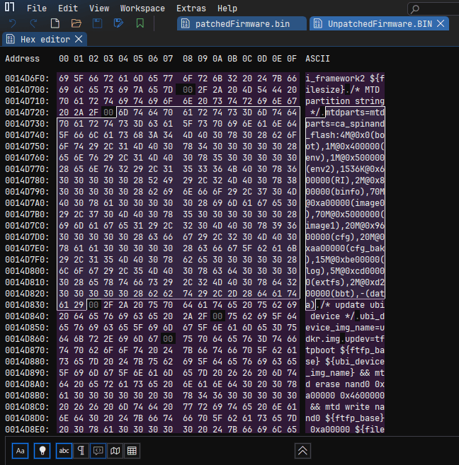
After parsing the mtdparts, the flash layout becomes much clearer. Each partition has a defined offset and role in the system:
| Partition | Offset | Size | Description |
|---|---|---|---|
| boot | 0x00000000 | 4M | Bootloader |
| env | 0x00400000 | 1M | Environment variables |
| env2 | 0x00500000 | 1M | Backup environment |
| RI | 0x00600000 | 1536K | Runtime information |
| binfo | 0x00800000 | 2M | Board information |
| image0 | 0x00A00000 | 70M | Primary firmware image |
| image1 | 0x05000000 | 70M | Secondary firmware image |
| cfg | 0x09600000 | 20M | Configuration storage |
| cfg_bak | 0x0AA00000 | 20M | Configuration backup |
| log | 0x0BE00000 | 15M | Logs |
| extfs | 0x0CD00000 | 5M | Extended filesystem |
| bbt | 0x0D200000 | 2M | Bad block table |
| data | 0x0D400000 | Remaining | User / runtime data |
I focused on the regions around 0x00400000 and 0x00500000, which correspond to the environment partitions. Those partitions are generally not signed because they contain a CRC to validate the data intergrity. Using the hex editor, I limited the view between these two offsets to avoid noise and concentrate only on relevant data. After scanning carefully, I found that the actual env1 data starts at offset 0x00440000, while env2 begins at 0x00550000.
Comparing both regions revealed something interesting: the content was almost identical, with only a single byte difference. This strongly suggests a redundancy mechanism. The bootloader likely validates env1 first, and if something looks wrong, it falls back to env2 as a backup. This explains why two environment partitions exist in the first place.
From a modification perspective, this means any change must be applied to both env1 and env2. Since the bootloader could detect the mismatch and revert to the untouched copy. To keep the system consistent, both partitions need to be aligned so the boot process accepts the modified environment without triggering the fallback logic.
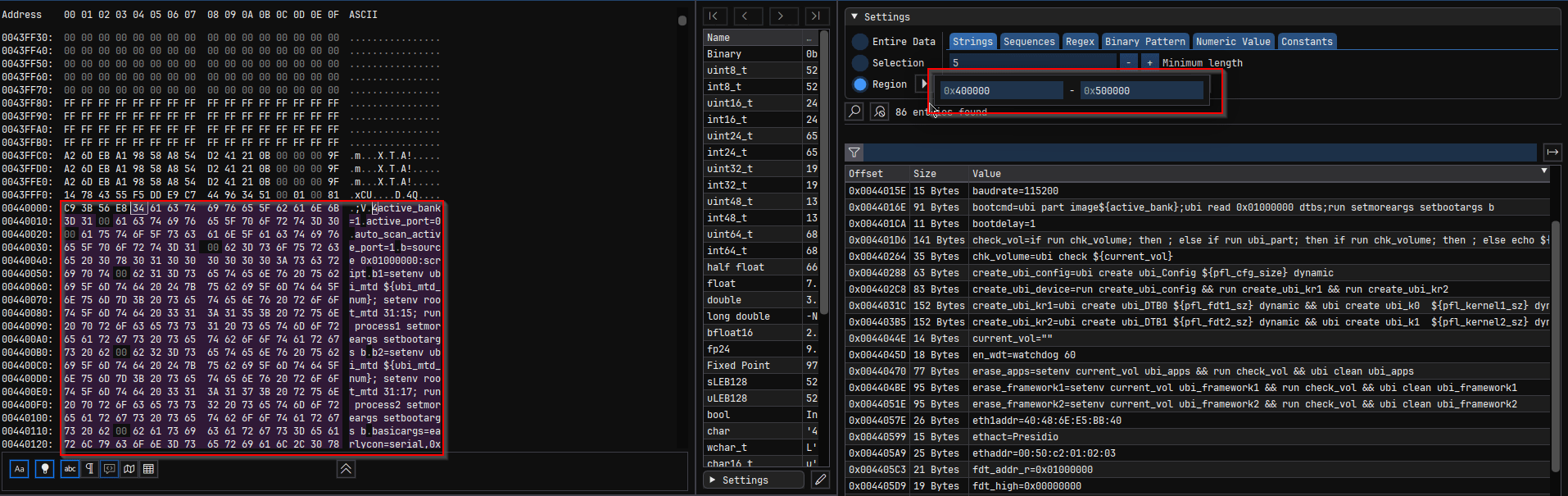
I was curious about the first 5 bytes at 0x440000. I asked chatGPT for env format in U-Boot :
+------------------+
| CRC32 (4 bytes)  |
+------------------+
| flags (optional) |
+------------------+
| key=value\0      |
| key=value\0      |
| key=value\0      |
| ...              |
| \0               |
+------------------+
| padding (0xFF)   |
+------------------+

//Structure of the page with CRC - Check page Activate shell and discussion with claude
struct env_t {
      uint32_t  crc;     // offset +0, 4 bytes
      uint8_t   flags;   // offset +4, 1 byte (only with redundant env)
      uint8_t   data[];  // offset +5, env key=value pairs
};The first 4 bytes contain the CRC32 checksum for ENV1. We must generate a new CRC32 for every modified ENV1 to maintain data integrity. Otherwise, the router will continuously reboot or enter fallback mode. The flag indicates to U-Boot which copy is the newest valid version. To decide whether the flag needs updating, I calculate the CRC32 of ENV1 excluding both the flag and the OOB area. I used an AI-generated Python script for this 🥴 (Don’t hate me — it’s fast 🤖)
I searched for “serial_is_dis” in the strings, I was thinking if I change it to 0 maybe it will activate the serial but it’s not the case. Each time I boot I found the serial_is_dis is equal 1. I have to search further, so the message “Serial console Disabled” is my target. I tried to use Claude to analyse the binary and understand a bit. In parallel, what I did is to patch once at a time every variable that I can change from 1 to 2 and vice versa and it must be in the ENV offsets.
I search in the hex strings for (“=0”, “=1”, “=2”). I found the variable “secboot=2” 🧐 Hmm, I said to myself what happens if I change that to 1 or 0 ? Let’s do it anyway I have a firmware backup if anything happens I can rollback 💪
Patching the firmware:
I create a code that you will find https://github.com/warber0x/NokiaBeacon3.1_Nand_Patcher/blob/main/NokiaBeaconBaker.py to patch the firmware. The code changes secboot from 2 to 1, injects init=/bin/sh in the kernel arguments and calculate the CRC.
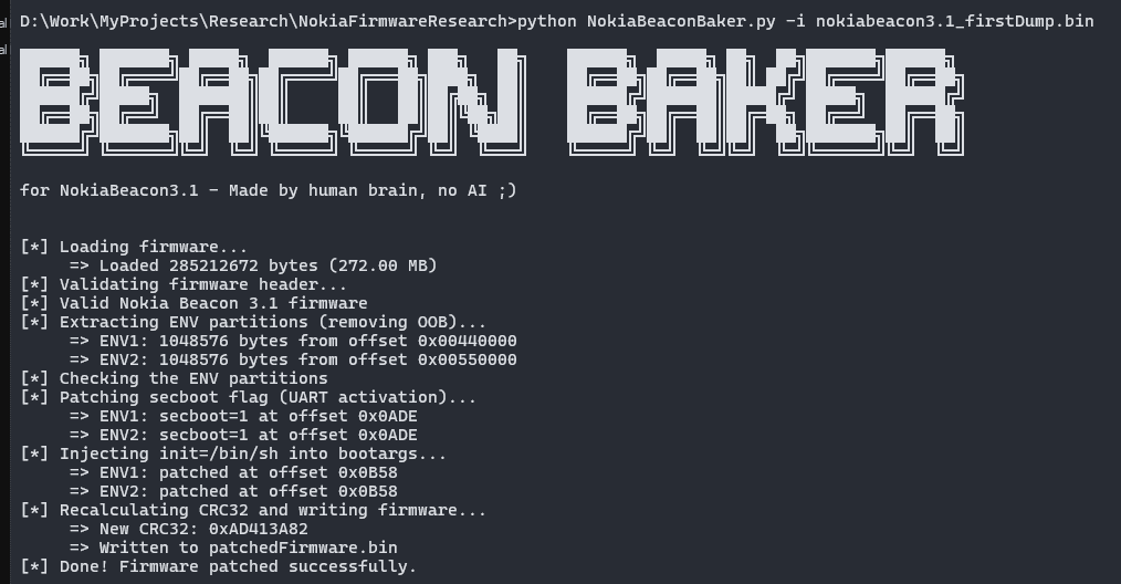
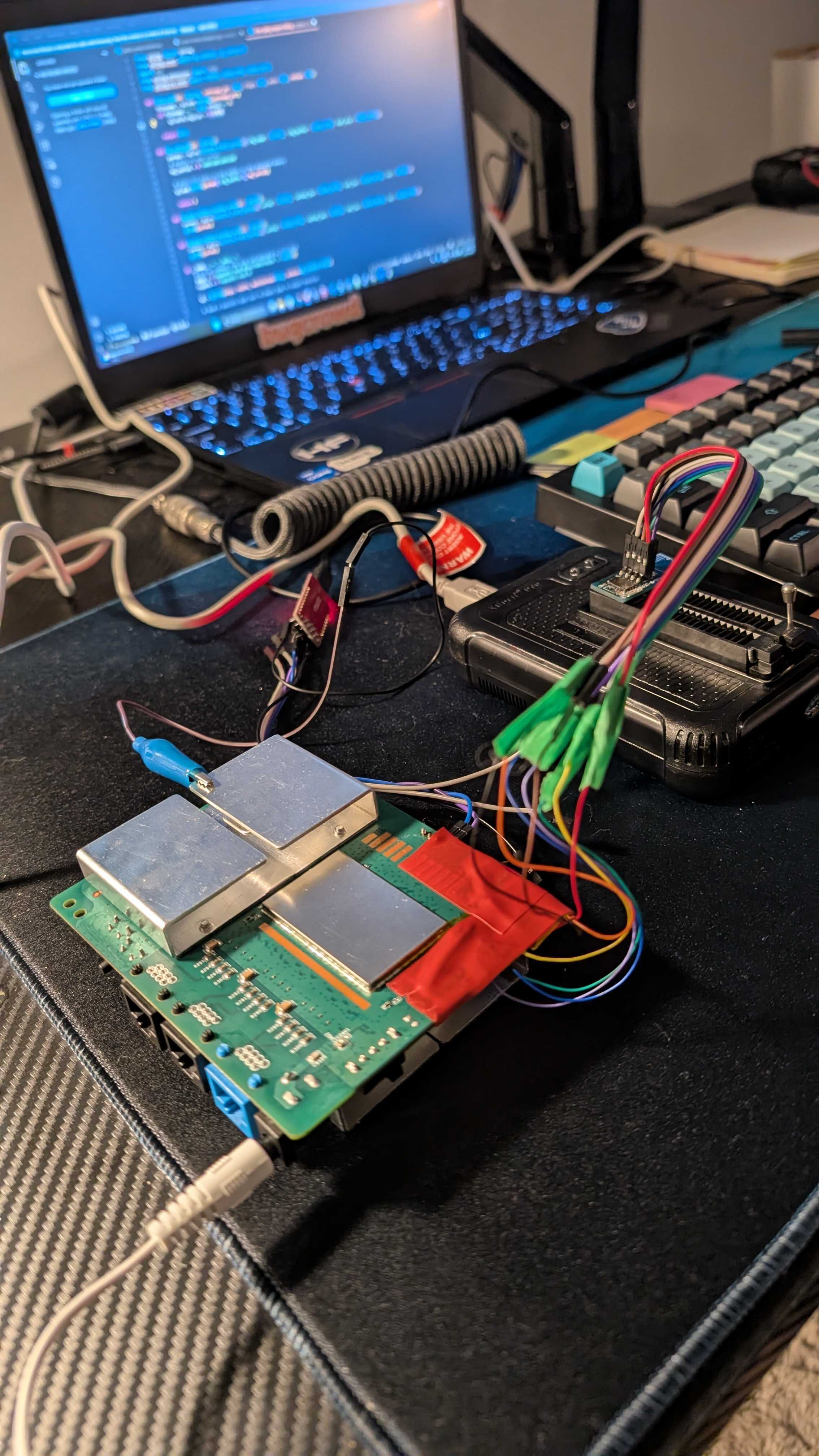
After patching it, I write the new firmware back to the NAND. I connect the router to the FTDI and:
U-Boot 2020.01 (Jul 24 2025 - 18:35:30 +0800)Taurus-SoC(OPTEE)

CortexA55: 1000 MHz
DDR4-1866: 16-bit mode, 512 MiB
NAND:  scan_spi_nand_factory_bad_blocks[899]: found list
SPI  NAND: MT29F2G01ABAGDWB/F50L2G41XA/XT26G02ELGIGA/WSFVC32GBID (0x2c24)
    spare: 0x80      (128B)
     page: 0x800     (2KB)
    block: 0x20000   (128KB)
     chip: 0x10000000(256MB)
available: 0x10000000(256MB)
     mode: S/S
    clock: 100 MHz
      BBL: Bbl0 from flash
   Hidden:
NAND:  256 MiB
Loading Environment from NAND... OK
enter console_disable_check
check_parts[2110]: not change
console_disable_check[48]: SN:
check_parts[2110]: not change
secboot is 1
>>>>>>>> Serial console Enabled <<<<<<<<  🎉🎉🎉🎉🎉🎉🎉🎉
enter update_basic_args
update_basic_args: enable serial, starbranch buf=earlycon=serial,0xf43291b0 console=ttyS0,115200
after update basicargs: earlycon=serial,0xf43291b0 console=ttyS0,115200
eixt update_basic_args
In:    serial
Out:   serial
Err:   serial
check_parts[2110]: not change
read boot info from nand success...
image0: 3TN00626IJLJ03 image1:3TN00626IJMJ28  crc:0x586a2760
System boot normal !
Boot fail 0 times...
reboot_reason reg:0xf4320194 value:0x0.
check_parts[2110]: not change
Erasing at 0x800000 -- 100% complete.
write boot info success...
check_parts[2110]: not change
current boot partition is image1


 Write hash key to OTP to enable secboot...
The Serial console is enabled and I got a shell : 🎉🎉🎉🎉🎉🎉🎉🎉
[   10.207898] ubi0 warning: ubi_open_volume.part.0: cannot open device 0, volume 3, ret -16
[   10.313320] VFS: Mounted root (squashfs filesystem) readonly on device 254:0.
[   10.320531] Freeing unused kernel memory: 448K
[   10.361003] Run /bin/sh as init process


BusyBox v1.35.0 (2023-01-03 00:24:21 UTC) built-in shell (ash)

/bin/sh: can't access tty; job control turned off
/ #
In this first part, we successfully obtained a shell by analyzing the raw NAND image and understanding the different firmware layers and partition layout 🔍. Through this analysis, we identified how the bootloader environment is structured, why the serial console is disabled by default, and which environment variables are responsible for controlling UART access. After locating these controls, we modified the relevant parameters and patched the firmware while preserving the NAND structure, redundant environment blocks, and CRC integrity ⚙️. This allowed us to re-enable the serial console and inject a boot argument that spawns a root shell during the boot process 🐚.
In the second part, I will demonstrate how to physically start the router, walk through the entire boot sequence, and disable the Quagga shell to gain deeper system control 🚀. Until then, stay tuned see you soon 👋.
Categories: IoT Reverse Engineering
Waiting for part 2 on the same boat unable to disable quagga
Hi, thanks for your comment. I’m taking some time to build a tool that disables Quagga and starts an SSH daemon instead. Stay tuned !!
we have these lying around. actually, it contains service provider firmware. and we cannot change wan settings etc.
can we flash the nokia default firmware on this.
Thanks
Flashing the firmware with another one is very risky and can break your device. I prefer avoiding it for the moment. I try to get a similar router to test that path… I’m working on a tool that lets you enable or disable certain features on your router, but it may not work for certain firmware versions. Stay tuned and check my github for updates !! cheers 😉
I have same device with isp firmware
How to unlock
Second part kab daalo ge bro kya ese admin ya root password nhi mila kya
There’s no universal root password for this router like people think. ISP devices are mostly locked through firmware and remote management. I’m working on a tool to adjust some internal settings where possible, but it depends heavily on the firmware. Stay tuned !!
I have Nokia 321NK router. I changed operator Id from ALCL to 0000. Now my router is not booting up. Webui is accessible but I don’t know credentials moreover When I put admin admin. I get error something went wrong. On telnet I am getting OpenWrt Login. Unaware about credentials. Can you help me with this bro. I am unable to find out any handle to contact you.
Can you share your GitHub url, I have a locked one UART disabled I have admin password but don’t know superadmin password I can’t do frimware extraction like you atleast I want is the superadmin password can you tell how can I get, also please share your superadmin password
The link is already in the article, but here it is again: https://github.com/warber0x/NokiaBeacon3.1_Nand_Patcher/blob/main/NokiaBeaconBaker.py
You have to know that each router comes with its own root password. There is no universal password for all Beacon 3.1 routers.
I will drop Part 2 soon, where I’ll also share a tool to disable Quagga. However, it seems the latest patch from Nokia has fucked up my strategy. Stay tuned!